A question that often comes up when obtaining used HP power meter heads at swap meets is how to test them to make sure they aren't bad. There is a simple test to verify that the thermistors aren't burned out. Of course, this procedure doesn't guarantee that something else isn't broken in the sensor, but this is a place to start.
The power sensor consists of two bridge circuits with a thermistor in one leg of each bridge. One bridge circuit is used to do the actual power measurement, while the other circuit is used to compensate for thermal drift due to ambient changes in the housing. In order to properly zero the meter and measure power, both bridge circuits must be working.
When no RF power is being applied to the thermistor head, both thermistors measure about the same value. When power is applied to the RF sensing bridge, its value changes and the difference is used to calculate the actual RF power. So all we need to do to test the power meter head is measure the resistance of the thermistors with no RF or DC power applied.
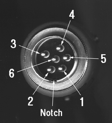
With the RF connector facing away from you, place the notch on the round cable connector so that the orientation notch is toward the bottom. Pin 1 will be on the bottom just to the right of the orientation notch. count clockwise around the outside pins to locate pins 2 through 5. Pin 6 is the pin in the center. Connect the negative lead of your ohmmeter to pin 6 (the center pin). This is the common return for both thermistors. Now, measure the resistance on pin 1 and pin 3. Both of these resistances should be within about 10%. If it is significantly outside of this range, the sensor is probably bad. Sometimes sensors that measure slightly outside this range can be adjusted, but that is a job for the experts. Of course, if your power sensor is really bad, you could use it as a housing for a homebrew noise source.
The above information was supplied by Lars, AA6IW

Ever wonder how to test a millimeter wave power meter head if you don't yet have access to an RF source at that frequency?
There are some (rare) occasions when Hughes or HP millimeter wave heads for HP-431 or 432 meters show up in surplus or at swap meets. The procedure outlined above meets most requirements for checkout, but there is one additional trick that I tried that seems to work when you don't have a millimeter wave RF signal source. I discovered this by accident one day when I was trying to test out some goodie that I acquired in surplus.
When peering into the end of the power sensor waveguide with a flourescent magnifying lamp I noticed the power level went up when I got it near the lamp. Then I grabbed a small flashlight and pointed it into the end of the waveguide, and that seemed to work also. It seems that the power detecting resistive element is directly coupled into the waveguide, and therefore responds not only to RF energy, but also to heat as well. This technique does not seem to work with diode sensors or ones that use a probe in the waveguide, but seems to be useful for the older style (HP 432) power sensors. Note that the power meter should be set to its most sensitive range. I have used this technique to test out some K, V and W band sensors. The high band sensors are more difficult to test because the waveguide is very narrow, and you have to shine the beam very accurately. You do not have to remove the protective foam from the end of the waveguide.
Please let me know how this works for you! Brian W6BY