|
Comments on the Yaesu FTV-1000 6 Meter Transverter
|
|||||||||||||
 |
|||||||||||||
|
W3RJW, Ron J. Whitsel
|
|||||||||||||
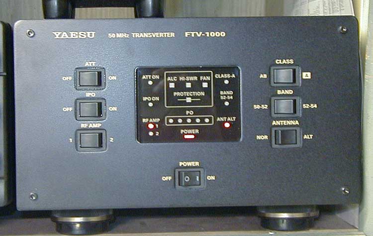
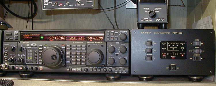
| The FTV-1000 6 meter transverter is designed to be used with only the FT-1000MP Mark V low frequency transceiver. It puts out a tidy 180 Watts (200 watts advertised) on 50 to 54 MHz. It is a high-end solution to getting on 6 meters, but if you already have a Mark V it’s a really nice luxury to own. There are a couple of things that need to be mentioned up front: The unit does not match the Mark V in appearance very well. In fact, it is a throwback to the early Yeasu radios that used stamped metal housings and rather plain graphics. To the point, the lettering is a gold color totally different then the off white lettering on the Mark V. The front panel is just a flat sheet of metal much like you would use when building something in your basement. Where are the sleek cast panels we have come to expect from today’s radios? |
|||||||||||||
 |
|||||||||||||
| Another disappointing feature is that the Mark V display does not automatically switch to indicate 50 MHz when you turn on the transverter. This is 2002 and I know the technology exists to do this without the manual process that is currently required with the Mark V/FTV-1000 combination. These things are indeed cosmetic and do not impact operation, but when you spend $900.00 for a six-meter transverter, your expectations tend to be pretty high The transverter works just fine. The controls are convenient and functional. The choices of operating parameters from the front panel allow for just about any scenario you can dream up. The receive part of the transverter works well with no birdies that I could find and more then enough gain. In fact about 15 dB too much gain. That subject in a moment. The transmitter "only" puts out 180 Watts, which seems to be limited by the ALC circuit. There is a pot to adjust the ALC feeding back to the Mark V to control the maximum power, however even with the pot at its endpoint, the full 200 watts could not be obtained. Removing the ALC cable allowed the transverter to produce well in excess of 200 watts. However, in the interest of equipment longevity, the only real difference between 180 watts and 220 watts will be apparent only to the person staring at the wattmeter. I guess the $900.00 perfection thing just bites at you! There are several diagrams in the FTV-1000 manual showing how to connect it to the Mark V. As far as I am concerned there is only one way that makes sense (that way is not shown in the ‘FTV-1000/MarkV’ diagram, although it is alluded to in the text). The 6 meter antenna coax should go to the "Alternate" antenna jack and the HF antenna coax goes to the "Normal" antenna jack, both on the back of the FTV-1000. A third cable comes from the Mark V antenna jack, A or B, (where you would normally connect your HF antenna) and goes to the "Transceiver" jack on the FTV-1000. This way when you turn the transverter off you return to HF operation automatically. When you turn the transverter on, the HF is disconnected and you are on 6 meters with the right antenna. One remaining problem is that if you use a linear on the low bands, the amplifier keying is not disconnected when you go to six meters. Maybe this is done this way because you are "suppose" to use the Yaesu VL-1000 amplifier that also does 6 meters. Maybe next year when I hit the lottery! In the mean time, turn off the low band amp. On the subject of receive gain, the FTV-1000 comes well equipped. I don’t know why, but the conversion gain is way more then can be handled by the Mark V. The recommended operating procedure is turn off the Mark V preamp (IPO "on") when operating with the FTV-1000. I found this to have two problems: 1) There is just not quite enough gain with the IPO on and 2) it’s a pain to have to remember to change the setup on the Mark V whenever the transverter is used. Again this is 2002 and the FTV-1000 is for exclusive uses with the Mark V. Why not make it fully compatible? My solution to this inconvenience was to install a fixed attenuator inside the FTV-1000. This way when I switch to 6 meters, I don’t have to do anything with the Mark V. There is already a factory built in 6 dB attenuator on the 28 MHz IF output. I added 15 dB more attenuation (are you adding things up here?) to make the Mark V happy (I use the "tuned" preamp setting in the Mark V). One may want to experiment with other values that will make you happy with your particular setup.
|
|||||||||||||
 |
 |
||||||||||||
|
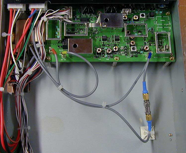
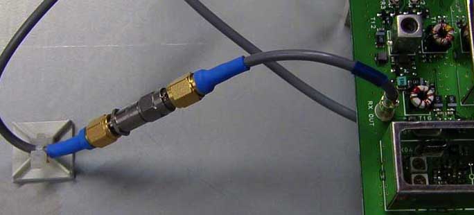
I cut the existing coaxial cable coming from the "RX Out" port and installed SMA cable plugs (bottom compartment). The cable is the typical gray stuff found in Japanese radios. It is close enough in size to RG-174 that connectors made for RG-174 will work. A fixed value SMA attenuator can then be inserted between the ends to set the gain. If you know a source for the Japanese style plug-in RF connectors (I don’t), you could make an attenuator from resistors that would then not necessitate cutting the factory cable. To restore to factory configuration, replace the attenuator with a female SMA barrel. |
|||||||||||||