![]()
For 432 MHz
by
Ron Whitsel, W3RJW
![]()
For 432 MHz
by
Ron Whitsel, W3RJW
It seems the modifications to the venerable Fair Radio FAA amps for use on 432 has been lost in space. Following are the modifications required to make either of these units work on 432 MHz. There are two keys to a successful 432 modification: 1) Remove the original grid circuit components completely and install a hobby brass stripline in its place and 2) Use a Teflon "cocoon" to insulate a new RF choke that must be installed in the plate circuit. Save yourself some time and trouble (Trouble Defined As: Massive quantities of black, sooty carbon material fused to the inside of the plate cavity resonator caused by the catastrophic disintegration of the plate choke and the non-Teflon insulator.) ; Teflon tape doesn’t work, heat shrink tubing doesn’t work - a hollow Teflon cylinder does work.
The basis for these modifications were originally described by WA5VJB in the November, 1985 issue of ‘VHF/UHF and Above’. A follow-up article by K0TLM in 1985 (VHF/UHF and Above?) solved the grid circuit problem. The information presented here borrows the best from both articles, adds some new ideas and attempts to describe all the information you will need for a successful conversion in one place. One of the major weak points of all the original conversions was the plate choke insulation. The technique described here solves that problem. A lathe is required to manufacture the Teflon plate choke insulator. A small hobby lathe such as a Unimat will do the job. I haven’t found any way around the insulator fabrication requirements and the Teflon insulator is absolutely essential to make this conversion work. I have personally modified about dozen 6154/55’s over the years and all work well, 12-15 watts of drive will produce 400 to over 500 watts of output depending mostly on the condition of the tube.
The power supply modifications have been well documented. Be sure to replace R1 and R2, 1/2 watt 10 ohm high voltage power supply resistors, with 2 watt 10 ohm resistors and use a heavy gauge wire to ground the ends of these resistors. I would also recommend that you run any of these amplifiers on 220 VAC, particularly a 432 unit which tends to draw a little more current because of reduced efficiency of the cavity at this frequency. The rest of the power supply conversions will not be given in this article. (Click here for W3RJW Power Supply Notes)
Getting Started:
1. Remove the RF plug-in from the chassis and remove the tube, the Teflon chimney and the plate ring by unscrewing two screws that attach it to the high voltage side of the plate bypass capacitor. Leave the plate side of the tube compartment alone for the moment and turn the unit over exposing the grid side of the compartment.
2. Remove the following components:
| AM-6154 | AM-6155 |
| C2 - Input Loading Cap, shaft and gears | C2 - Input Loading Cap, shaft and gears |
| R1 - 47K 1/2 Watt Input to ground | C3 - 3.3 pf Grid Line to Grid |
| C3 - 15pf Grid Line to Grid | L1,L2 - .22 µh RF Choke and Bead |
| C5, C6, C7 6.8 pf Caps | E1 - Spark Gap |
| L1,L2 .22 µh RF Choke and Bead | External Bandpass Filter |
| E1 - Spark Gap | |
| External Bandpass Filter | |
| R2,R3,R4,R5 Remove 20 ohm Cathode Resistors & Solder Cathode Pins to Ground |
3. Remove the small "c" clip from the shaft of the grid tuning capacitor. The clip is located at the gear end of the shaft, near the front panel. Also, loosen the set screws that hold the gear to the shaft. Removing the clip and loosing the gear will allow you to slide the whole shaft assembly forward, through the gear, far enough to disengage the shaft from the black coupling tube that connects the drive shaft to the tuning capacitor shaft.
4. If you have removed all the components listed above and completed step 3, you can now remove the entire grid compartment by removing the four screws that hold it to the main chassis and remove the two screws that hold the feedthru capacitor plate to the grid compartment. Leave the feedthru capacitor plate where it is as you lift up and remove the entire grid compartment.
5. Unsolder the tuning capacitor (C1) rotor from the grid line. Unscrew the nut that holds the tuning capacitor to the side wall of the compartment. Remove the capacitor and set aside, this will be modified and reinstalled.
6. The input pedestal inductor has to be removed from the input cavity. This can be a real bear depending on the state of the set screws that hold the pedestal to the cavity at the cold end. Extreme cases require drilling out the set screws. Once the set screws are loosened, slide the pedestal out of the cavity and unscrew at the thread joint. Saw off an inch or so of the grid line to put back in the hole where the set screws are located. Plug the hole and tighten the set screws. The only component remaining in the grid compartment at this point should be the TNC RF input jack.
This completes the removal process. It’s now time to prepare for the new parts process.
7. Modify the old tuning capacitor by removing about half the plates on either the stator or rotor. This is not absolutely essential, but makes the tuning less "sharp". I have a band saw that I use to carefully saw off the stator posts so that 3 or 4 of the stator plates remain. A sharp hack saw can be used very carefully. Another alternative is to replace the capacitor with a small value model with about 3 or four plates. These miniature variables used to be quite popular for the "6360" AM rigs that were in the old ARRL handbooks. Usually available at Hamfests for cheap. What ever method you use, make sure to check the capacitor for shorts between the stator and the rotor. You can see how close the plates are together. Rotate the capacitor through its entire range while looking for shorts with an ohm meter.
8. Reinstall the modified capacitor (C1) in its old spot in the grid compartment. Install a 200 pf silver mica capacitor from the grid bias input (C4) to ground (rim of tube socket). Reinstall the entire grid compartment. Push the shaft back into the coupling and put the 'C' clip back on the shaft, tighten the set screws in the gear hub, and check that turning the input tuning control turns the capacitor. It wouldn’t hurt to check for shorts again.
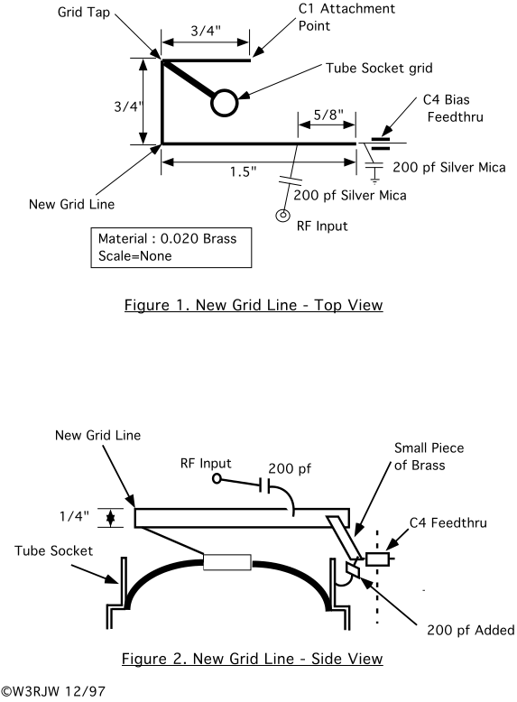
9. Cut out the new grid line and bend to shape according to Figure 1 and Figure 2. Nothing is really critical here so don’t spend a lot of time agonizing over the dimensions. Things can be fitted and trimmed as necessary when installing.
Now comes the fun part:
10. Position the new grid line inside the grid compartment level with the tab on C1 and solder at three points: the grid bias feed through capacitor (C4), the tuning capacitor (C1) and to the tapped connection from the grid line to the tube grid connection. The C4 and grid tap connections are made with small strips of brass material. Install another 200pf silver mica from the RF input to the tap point on the line. See Figure 2.
Back to the Plate compartment:
11. Remove the two screws that attach the ends of the high voltage capacitor plate assembly to the two vertical insulators on either side of the plate line. Next remove the two screws that attach the capacitor plate assembly to the plate line. Make sure you remember which screws go where.
12. Remove the high voltage side of the bypass capacitor plate by heating the nipple in the center of the plate with a soldering iron and at the same time apply steady pressure to pull the assembly free when the solder melts. Remove the Kapton (?) (Orange film) or Mica dielectric material and the small Teflon bushing that the high voltage wire passes through. Remember the orientation of the bushing. Place the parts in a clean, safe location.
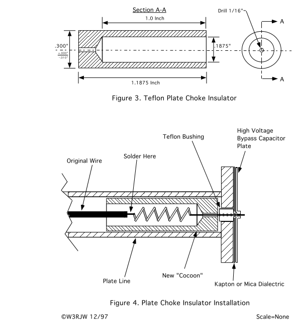
13. Manufacture the plate choke insulator as shown in Figure 3. (Note: Teflon stock is available from McMaster-Carr Supply Co.: http://www.mcmaster.com/)
14. At the front panel end of the cavity, unsolder the high voltage lead from the feed through capacitor. Make sure the cavity band change "switch" is in the "VHF" position. Remove the post (mounting plate to front panel) above the plate tuning counter and loosen the set screws on the plate tuning gear. Slip the tuning gear off its shaft and slide it on to the flexible tuning shaft to make room for the wrench in the next step. Put a wrench (1/2" cheap, stamped wrench works best here) on the feed through capacitor and start to loosen the capacitor. Once the capacitor is "broken loose", use the wrench to hold the feed through capacitor, and with the other hand grasp the plate compartment end of the plate line and start to unscrew the capacitor from the front end of the cavity. This is a little tricky the first time you do it, but be assured you will be able to "unscrew" the feed through capacitor from the front end of the cavity by turning the plate line at the other end (lots of turns). Once unscrewed, draw the capacitor and attached wire out the full length of the cavity.
15. Prepare an air wound choke from bare #20 wire that is 5 turns, spaced about one wire diameter, and has an ID of 7/64 inch (use a 7/64" drill bit). Leave about one inch of lead on one end and about 1/8 inch on the other end. Stretch out the feedthru capacitor and attached wire to its full length. Mark the length from the shoulder of the feed through capacitor to the tip of the wire on the workbench top or a piece of cardboard (about 11.25 inches). The idea is going to be to try and match capacitor, wire and new choke assembly length to the original length of just the capacitor and wire. To do this lay the choke on the table with the long lead of the choke about an eighth of an inch past the total length mark. Tape the choke to the table or card board in that position. Now stretch out the wire and capacitor assembly again, position the capacitor in the same place as before and mark the wire for cutting at a point where it just overlaps the short choke lead. Cut the wire, strip the end and solder it to the choke. You should now have a capacitor, wire and choke assembly ready for insertion back into the plate line.
16. Slip the Teflon ‘cocoon’ over the choke all the way so the bare wire from the long lead of the choke sticks out through the end of the ‘cocoon’. Insert the whole assembly, cocoon first, back into the plate line (see Figure 4.). Push it all the way in until you get to the point where the capacitor threads are ready to be screwed back into the front end of the plate cavity. Reverse the removal procedure and screw the plate line on to the capacitor. Once close to being tight, check to see that the two screw holes in the end of the plate line are parallel to bottom of the compartment (sight along the edge of the compartment). This takes some 'messing' around until you get the capacitor tight at the same time the screw holes are in the right position. The final tightening is accomplished with a wrench on the capacitor. Undershooting the final position of the screw holes and then turning the capacitor in the last little bit with the wrench sometimes works.
17. Remove all the solder from the center hole in the high voltage capacitor plate. This is accomplished most of the time by simply drilling the old solder out with a small drill bit (It's hard to get enough heat and suck solder at the same time).
18. Clean the end of the plate line, the dielectric disk and the backside of the high voltage capacitor plate with video tape head cleaner or 200 proof alcohol, something that leaves no residue. Make sure these parts are absolutely clean to prevent a stray particle from initiating a high voltage "punch through".
19. Place the small Teflon bushing back into the end of the plate line. If you have difficulty pushing this bushing all the way in (there will be some resistance), then the wire is probably a bit too long and must be shortened. Position the dielectric disk so that it is centered on the plate line with the tip of the bushing and wire protruding through its center. The screw holes in the dielectric disk must also be aligned with the screw holes in the end of the plate line.. Place the high voltage capacitor plate over the wire and up against the plate line without moving anything (easier said then done). When every thing is back in place reinstall the two attaching screws to the end of the plate line. Reinstall other two screws in the vertical insulators.
20. Using a large capacity soldering iron, solder the choke wire to the high voltage capacitor plate nipple. Trim any excess choke lead. From the outside everything should now look just as it did before modification. Reinstall the plate tuning gear and the support post removed in Step 14. Resolder the red high voltage lead to the feedthru capacitor. Use new heat shrink tubing to insulate the connection. Reinstall the plate ring and Teflon chimney and put the tube back in.
21. Put the cavity band switch in the "UHF" position. If you can't grid dip the input network, then preset the grid tuning capacitor to about the half meshed position. Preset the Plate loading capacitor to about half way.
Tune-Up
22. The moment of truth is here. Put the RF plug-in back in the chassis and turn on the power. Wait for the warm-up timer to time out and then turn on the high voltage. If there are no snaps, crackles or pops, all is well and right with the world. If not, then you have to open the patient back up and find out what’s wrong.
23. Most all the units I have used want the plate tuning to be at about '157' to '159' on the plate tuning counter. This is the place to start.
24. Start with reduced drive, if possible ( about 5 watts), and adjust the grid tuning for maximum current on the plate meter (Note: The grid tuning control will still be pretty sharp, even with the modified capacitor, so tune carefully and find the exact peak.). If you see power output at this point, then tune the plate for maximum output power. If you see plate current and no RF output then tweak the plate tuning and power should start to rise. Something should be happening at this point. If it's not, then step back for a moment and try to determine what might be wrong: Check the cables, any relays in the system or perhaps the drive is not what you think it is.
25. Raise the drive power and go back and forth between the plate tuning and loading controls to peak the power output each time you raise the drive (Note: The loading control is not that critical until you get near maximum power). Go back and touch up the grid tuning as power output starts to come up. Once some serious power starts to show (300 to 400 watts), I usually continue this procedure with an electronic keyer sending continuous dashes to reduce the power dissipation a little bit. The AM-6154/55 have a temperature shut down circuit so you will know if things get too hot. If the high voltage trips from over temperature, let it cool down (with the blower running) and then turn the high voltage back on in a few minutes. Do your tuning in short bursts. Give the tube a few seconds every now and then to get rid of some heat.
26. With 15 watts of drive and a good tube you should easily exceed 450 watts out. I would back it off a little to conserve both tube and power supply, but that depends on the depth of your pockets.
 |
||||
|
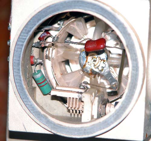
Picture showing inside of modified grid compartment.
Note plates removed on tuning capacitor and new by-pass cap on grid bias feed point (top left). Mica cap at top right is input coupling capacitor. |
||||
![]()